概述
基于 GEC Double Pi 母板的 STM 32 平台,使用 Keil 编辑编译代码,使用 FlyMcu 烧录程序。
编程语言:C 。
功能:实现小车的循迹、自动避障和蓝牙遥控。
核心代码文件结构:
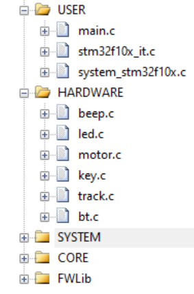
- beep.c — 蜂鸣器控制
- led.c — LED 灯控制
- motor.c — 电机控制
- key.c — 按键控制
- track.c — 小车循迹和避障控制
- bt.c — 蓝牙遥控控制
GPIO引脚
简介
GPIO:General Purpose Input/Output Pins(通用功能输入/输引脚 )。
引脚:从芯片内部引出来的,一根可以输入和输出复用的导线 。CPU 控制整个外围电路都是通过引脚来实现的。STM32F103 有 112 个引脚,分为7组,分别记为 GPIOA 、GPIOB 、GPIOC … GPIOG 。每组 16 个引脚, 编号从 0~15 ,例如 GPIOA0、GPIOA1 ,简记为 PA0 、PA1 。
功能
输出功能 写
输入功能 读
CPU 可以获取外部引脚的电平状态。
每一个引脚都有一个上拉电阻和下拉电阻,通过配置上拉电阻和下拉电阻,可以控制引脚的默认的电平状态。当开启上拉电阻时,引脚默认是高电平。当开启下拉电阻时,引脚默认是低电平。
输入悬空
disable 上拉电阻 disable 下拉电阻。
带上拉的输入
enable 上拉电阻 disable 下拉电阻。
带下拉的输入
disable 上拉电阻 enable 下拉电阻。
模拟输入
CPU 用此引脚来采集外部电路的模拟信号。
操作
使用官方库来操作 GPIO 。
初始化
使能 GPIO 分组和 AFIO 时钟:
1
2
3
4
5
6
7
8
9
10
11
12
13
14
15
| void RCC_APB2PeriphClockCmd(uint32_t RCC_APB2Periph, FunctionalState NewState)
参数:
RCC_APB2Periph 指定要使能时钟的外设名
- RCC_APB2Periph_GPIOA GPIOA时钟
- RCC_APB2Periph_GPIOB GPIOB时钟
- ...
- RCC_APB2Periph_AFIO 复用时钟
NewState 指定时钟的状态
- ENABLE 使能
- DISABLE 禁止
例子:
RCC_APB2PeriphClockCmd( RCC_APB2Periph_GPIOB|RCC_APB2Periph_AFIO , ENABLE );
|
禁用 Jtag 功能,把 PB3、PB4 等重新映射为普通 IO 口:
1
2
3
4
| void GPIO_PinRemapConfig(uint32_t GPIO_Remap, FunctionalState NewState)
例子:
GPIO_PinRemapConfig( GPIO_Remap_SWJ_JTAGDisable , ENABLE );
|
初始化 GPIO :
1
2
3
4
5
6
7
8
9
10
11
12
13
14
15
16
17
18
19
20
21
22
23
24
25
26
27
28
29
30
31
32
33
34
35
36
37
38
39
40
41
42
43
| void GPIO_Init(GPIO_TypeDef* GPIOx, GPIO_InitTypeDef* GPIO_InitStruct)
参数:
GPIOx 指定要初始化的GPIO分组
- GPIOA
- GPIOB
- GPIOC
- ...
GPIO_InitStruct 要初始化配置的结构体的地址
GPIO结构体说明:
typedef struct
{
uint16_t GPIO_Pin;
- GPIO_Pin_0
- GPIO_Pin_1
- GPIO_Pin_2
- ...
- GPIO_Pin_15
GPIOSpeed_TypeDef GPIO_Speed;
- GPIO_Speed_10MHz 中速率
- GPIO_Speed_2MHz 低速率
- GPIO_Speed_50MHz 高速率
GPIOMode_TypeDef GPIO_Mode;
- GPIO_Mode_AIN 模拟输入
- GPIO_Mode_IN_FLOATING 输入悬空
- GPIO_Mode_IPD 带下拉的输入
- GPIO_Mode_IPU 带上拉的输入
- GPIO_Mode_Out_OD 输出开漏
- GPIO_Mode_Out_PP 输出推挽
- GPIO_Mode_AF_OD 复用开漏
- GPIO_Mode_AF_PP 复用推挽
}GPIO_InitTypeDef;
例子:
GPIO_InitTypeDef GPIO_InitStruct;
GPIO_InitStruct.GPIO_Pin = GPIO_Pin_1;
GPIO_InitStruct.GPIO_Speed = GPIO_Speed_50MHz;
GPIO_InitStruct.GPIO_Mode = GPIO_Mode_Out_PP;
GPIO_Init( GPIOA, &GPIO_InitStruct );
|
读写操作
输入(读),获取一个 GPIO 引脚的电平状态:
1
2
3
4
5
6
7
8
9
| uint8_t GPIO_ReadInputDataBit(GPIO_TypeDef* GPIOx, uint16_t GPIO_Pin)
参数:
GPIOx : 指定引脚分组 GPIOA, GPIOB, ... GPIOG
GPIO_Pin : 指定引脚编号 GPIO_Pin_0, GPIO_Pin_1, ... GPIO_Pin_15
返回值:
1 高电平
0 低电平
|
输出(写),设置一个 GPIO 引脚的电平状态 :
1
2
3
4
5
6
7
8
9
10
11
12
13
14
|
void GPIO_WriteBit(GPIO_TypeDef * GPIOx, uint16_t GPIO_Pin, BitAction BitVal)
参数:
GPIOx : 指定引脚分组 GPIOA, GPIOB, ... GPIOG
GPIO_Pin : 指定引脚编号 GPIO_Pin_0, GPIO_Pin_1, ... GPIO_Pin_15
BitVal :
- Bit_RESET 0 低电平
- Bit_SET 1 高电平
void GPIO_SetBits(GPIO_TypeDef* GPIOx, uint16_t GPIO_Pin)
void GPIO_ResetBits(GPIO_TypeDef* GPIOx, uint16_t GPIO_Pin)
|
实现LED灯控制
led.h
1
2
3
4
5
6
7
8
9
10
11
12
13
14
15
16
17
18
19
20
21
22
23
24
25
26
| #ifndef __LED_H__
#define __LED_H__
#define LED1 1
#define LED2 2
#define LED3 3
#define LED4 4
#define LED5 5
#define LED6 6
#define LED7 7
#define LED8 8
#define LED_ALL 9
#define ON 1
#define OFF 0
void led_init();
void led_ctl(int LED_ID, int ON_OFF);
void water_led();
#endif
|
led.c
1
2
3
4
5
6
7
8
9
10
11
12
13
14
15
16
17
18
19
20
21
22
23
24
25
26
27
28
29
30
31
32
33
34
35
36
37
38
39
40
41
42
43
44
45
46
47
48
49
50
51
52
53
54
55
56
57
58
59
60
61
62
63
64
65
| #include "led.h"
#include "stm32f10x.h"
#include "stm32f10x_gpio.h"
#include "stm32f10x_rcc.h"
#include "SysTick.h"
#include "system.h"
void led_init()
{
GPIO_InitTypeDef GPIO_InitStruct;
RCC_APB2PeriphClockCmd( RCC_APB2Periph_GPIOB | RCC_APB2Periph_AFIO, ENABLE );
GPIO_PinRemapConfig( GPIO_Remap_SWJ_JTAGDisable , ENABLE );
GPIO_InitStruct.GPIO_Pin = GPIO_Pin_0 | GPIO_Pin_1 | GPIO_Pin_2 | GPIO_Pin_3 | GPIO_Pin_4 | GPIO_Pin_5 | GPIO_Pin_6 | GPIO_Pin_7 ;
GPIO_InitStruct.GPIO_Speed = GPIO_Speed_50MHz;
GPIO_InitStruct.GPIO_Mode = GPIO_Mode_Out_PP;
GPIO_Init( GPIOB, &GPIO_InitStruct );
GPIO_SetBits( GPIOB, GPIO_Pin_0 | GPIO_Pin_1 | GPIO_Pin_2 | GPIO_Pin_3 | GPIO_Pin_4 | GPIO_Pin_5 | GPIO_Pin_6 | GPIO_Pin_7 );
}
void led_ctl(int LED_ID, int ON_OFF)
{
SysTick_Init(72);
switch(LED_ID){
case LED1 : GPIO_WriteBit(GPIOB, GPIO_Pin_0, (BitAction)ON_OFF); break;
case LED2 : GPIO_WriteBit(GPIOB, GPIO_Pin_1, (BitAction)ON_OFF); break;
case LED3 : GPIO_WriteBit(GPIOB, GPIO_Pin_2, (BitAction)ON_OFF); break;
case LED4 : GPIO_WriteBit(GPIOB, GPIO_Pin_3, (BitAction)ON_OFF); break;
case LED5 : GPIO_WriteBit(GPIOB, GPIO_Pin_4, (BitAction)ON_OFF); break;
case LED6 : GPIO_WriteBit(GPIOB, GPIO_Pin_5, (BitAction)ON_OFF); break;
case LED7 : GPIO_WriteBit(GPIOB, GPIO_Pin_6, (BitAction)ON_OFF); break;
case LED8 : GPIO_WriteBit(GPIOB, GPIO_Pin_7, (BitAction)ON_OFF); break;
case LED_ALL: GPIO_WriteBit(GPIOB, GPIO_Pin_0|GPIO_Pin_1|GPIO_Pin_2|GPIO_Pin_3|GPIO_Pin_4|GPIO_Pin_5|GPIO_Pin_6|GPIO_Pin_7, (BitAction)ON_OFF); break;
default : break;
}
}
void water_led()
{
int i;
for(i=0; i<8; i++){
switch(i){
case 0 : GPIO_WriteBit(GPIOB, GPIO_Pin_0, Bit_RESET); delay_ms(50); GPIO_WriteBit(GPIOB, GPIO_Pin_0, Bit_SET); break;
case 1 : GPIO_WriteBit(GPIOB, GPIO_Pin_1, Bit_RESET); delay_ms(50); GPIO_WriteBit(GPIOB, GPIO_Pin_1, Bit_SET); break;
case 2 : GPIO_WriteBit(GPIOB, GPIO_Pin_2, Bit_RESET); delay_ms(50); GPIO_WriteBit(GPIOB, GPIO_Pin_2, Bit_SET); break;
case 3 : GPIO_WriteBit(GPIOB, GPIO_Pin_3, Bit_RESET); delay_ms(50); GPIO_WriteBit(GPIOB, GPIO_Pin_3, Bit_SET); break;
case 4 : GPIO_WriteBit(GPIOB, GPIO_Pin_4, Bit_RESET); delay_ms(50); GPIO_WriteBit(GPIOB, GPIO_Pin_4, Bit_SET); break;
case 5 : GPIO_WriteBit(GPIOB, GPIO_Pin_5, Bit_RESET); delay_ms(50); GPIO_WriteBit(GPIOB, GPIO_Pin_5, Bit_SET); break;
case 6 : GPIO_WriteBit(GPIOB, GPIO_Pin_6, Bit_RESET); delay_ms(50); GPIO_WriteBit(GPIOB, GPIO_Pin_6, Bit_SET); break;
case 7 : GPIO_WriteBit(GPIOB, GPIO_Pin_7, Bit_RESET); delay_ms(50); GPIO_WriteBit(GPIOB, GPIO_Pin_7, Bit_SET); break;
default : break;
}
}
}
|
实现蜂鸣器控制
beep.h
1
2
3
4
5
6
7
8
9
| #ifndef __BEEP_H__
#define __BEEP_H__
void beep_init();
void beep_ctl(int ON_OFF);
#endif
|
beep.c
1
2
3
4
5
6
7
8
9
10
11
12
13
14
15
16
17
18
19
20
21
22
23
24
25
26
27
28
29
30
31
32
33
34
35
36
37
38
39
| #include "beep.h"
#include "stm32f10x.h"
#include "stm32f10x_gpio.h"
#include "stm32f10x_rcc.h"
void beep_init()
{
GPIO_InitTypeDef GPIO_InitStruct;
RCC_APB2PeriphClockCmd( RCC_APB2Periph_GPIOA | RCC_APB2Periph_AFIO, ENABLE );
GPIO_PinRemapConfig( GPIO_Remap_SWJ_JTAGDisable , ENABLE );
GPIO_InitStruct.GPIO_Pin = GPIO_Pin_1;
GPIO_InitStruct.GPIO_Speed = GPIO_Speed_50MHz;
GPIO_InitStruct.GPIO_Mode = GPIO_Mode_Out_PP;
GPIO_Init( GPIOA, &GPIO_InitStruct );
GPIO_SetBits( GPIOA, GPIO_Pin_1);
}
void beep_ctl(int ON_OFF )
{
if(ON_OFF==1)
{
GPIO_WriteBit( GPIOA, GPIO_Pin_1, Bit_RESET );
}
else
{
GPIO_WriteBit( GPIOA, GPIO_Pin_1, Bit_SET );
}
}
|
实现按键控制
key.h
1
2
3
4
5
6
7
8
9
10
11
12
13
14
15
16
| #ifndef __KEY_H__
#define __KEY_H__
#define KEY1 GPIO_ReadInputDataBit(GPIOA, GPIO_Pin_13)
#define KEY2 GPIO_ReadInputDataBit(GPIOA, GPIO_Pin_2)
#define KEY3 GPIO_ReadInputDataBit(GPIOA, GPIO_Pin_6)
#define KEY4 GPIO_ReadInputDataBit(GPIOA, GPIO_Pin_7)
void key_init();
void key_ctl_led_beep();
void key_ctl_motor();
#endif
|
key.c
1
2
3
4
5
6
7
8
9
10
11
12
13
14
15
16
17
18
19
20
21
22
23
24
25
26
27
28
29
30
31
32
33
34
35
36
37
38
39
40
41
42
43
44
45
46
47
48
49
50
51
52
53
54
55
56
57
58
59
60
61
62
63
64
65
66
67
68
69
70
71
72
73
| #include "led.h"
#include "beep.h"
#include "key.h"
#include "motor.h"
#include "stm32f10x.h"
#include "stm32f10x_gpio.h"
#include "stm32f10x_rcc.h"
#include "SysTick.h"
#include "system.h"
void key_init()
{
GPIO_InitTypeDef GPIO_InitStruct;
RCC_APB2PeriphClockCmd( RCC_APB2Periph_GPIOA | RCC_APB2Periph_AFIO, ENABLE );
GPIO_PinRemapConfig( GPIO_Remap_SWJ_JTAGDisable , ENABLE );
GPIO_InitStruct.GPIO_Pin = GPIO_Pin_2 | GPIO_Pin_6 | GPIO_Pin_7 | GPIO_Pin_13;
GPIO_InitStruct.GPIO_Speed = GPIO_Speed_50MHz;
GPIO_InitStruct.GPIO_Mode = GPIO_Mode_IPU;
GPIO_Init(GPIOA, &GPIO_InitStruct );
}
void key_ctl_led_beep()
{
while(1){
if(KEY1==0){
led_ctl(9, 1);
}
else if(KEY2==0){
led_ctl(9, 0);
}
else if(KEY3==0){
beep_ctl(1);
}
else if(KEY4==0){
beep_ctl(0);
}
}
}
void key_ctl_motor()
{
while(1){
if(KEY1==0){
move_front();
}
else if(KEY2==0){
move_back();
}
else if(KEY3==0){
move_left();
}
else if(KEY4==0){
move_right();
}
}
}
|
直流电机
直流电机正向通电就会正转, 反向通电就会反转,两极的电势差决定转速。
原理说明及接线:
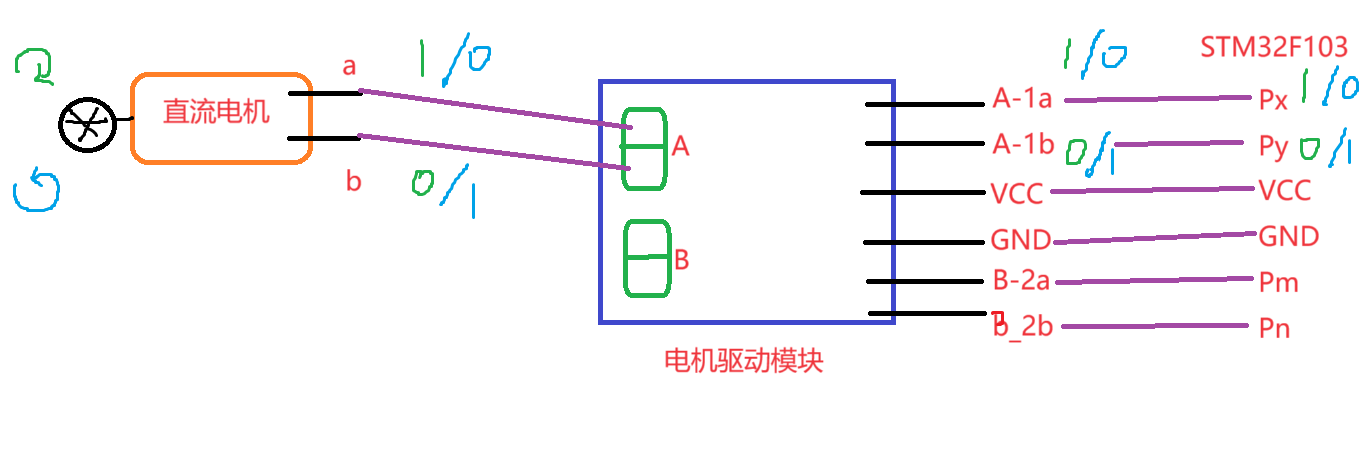
前进:左右电机正转。
后退:左右电机反转。
左转:左电机停止、右电机正转 或 左电机反转、右电机正转(转弯半径更小)。
右转:右电机停止、左电机正转 或 右电机反转、左电机正转(转弯半径更小)。
停止:左右电机停转。可通过先执行后退一小段时间,缓冲掉惯性,再执行停止来减小制动距离。
掉头:执行左转或右转一段时间,待车头掉转摆正。
循迹和避障
循迹与避障需要使用红外对管来识别轨迹或障碍物。
红外对管由红外发射管和红外接收管组成,红外对管连接在红外主控板上。通电时,红外发射管不断地往外发射红外光线,红外接收管不断地接收反射回来的红外光线。
当红外接收管能够接收到反射时,红外对管的引脚电平为 0 。当红外接收管不能接收到反射时,红外对管的引脚电平为 1 。
循迹时,红外对管要垂直于地面进行安装,主要是利用不同颜色的物体对于光线的反射和吸收程度不一样。白色物体能够反射大量的光线,吸收的比较少。黑色物体能够吸收大量的光线,反射的比较少。对于地面(白色),红外接收管能够接收到反射回来的光线,此时引脚电平为 0 。对于轨迹(黑色),红外接收管就收不到红外光线了,此时引脚电平为 1 。
避障时,红外对管要平行于地面进行安装,主要利用空气对于光线有一定削弱作用。当前面有障碍物时,红外接收管能够收到大量的红外光线,此时引脚电平为 0 。当前面没有障碍物时,红外接收管接收不到红外光线,此时引脚电平为 1 。
当小车速度过快时,会出现在循迹转弯时,小车转弯所耗路程过大而直接冲出轨迹或偏移轨迹,或小车停止制动距离过长等情况。可以利用脉冲宽度调制技术控制电机转速,减小小车转弯制动距离。
脉冲宽度调制技术:使用 delay 延时函数,使连续的电平信号调整为离散的脉冲信号。
小车运动方向判定:
| 左红外对管引脚电平 |
右红外对管引脚电平 |
运动方向 |
| 0 |
0 |
前进 |
| 0 |
1 |
左转 |
| 1 |
0 |
右转 |
| 1 |
1 |
停止或掉头 |
实现循迹和避障
电机控制
motor.h
1
2
3
4
5
6
7
8
9
10
11
12
13
14
15
16
17
18
19
20
21
22
23
24
25
26
27
28
29
| #ifndef __MOTOR_H__
#define __MOTOR_H__
void motor_init();
void set_left_a(int n);
void set_left_b(int n);
void set_right_a(int n);
void set_right_b(int n);
void move_front();
void move_back();
void move_left();
void move_right();
void stop();
void move_front_PWM();
void move_back_PWM();
void move_left_PWM();
void move_right_PWM();
void stop_PWM();
void move_return();
#endif
|
motor.c
1
2
3
4
5
6
7
8
9
10
11
12
13
14
15
16
17
18
19
20
21
22
23
24
25
26
27
28
29
30
31
32
33
34
35
36
37
38
39
40
41
42
43
44
45
46
47
48
49
50
51
52
53
54
55
56
57
58
59
60
61
62
63
64
65
66
67
68
69
70
71
72
73
74
75
76
77
78
79
80
81
82
83
84
85
86
87
88
89
90
91
92
93
94
95
96
97
98
99
100
101
102
103
104
105
106
107
108
109
110
111
112
113
114
115
116
117
118
119
120
121
122
123
124
125
126
127
128
129
130
131
132
133
134
135
136
137
138
139
140
141
142
143
144
145
146
147
148
149
150
151
152
153
154
155
156
157
158
159
160
161
162
163
164
165
166
167
168
169
170
171
172
173
174
175
176
177
178
179
180
181
182
183
184
185
186
187
188
189
190
191
192
193
194
195
| #include "motor.h"
#include "stm32f10x.h"
#include "stm32f10x_gpio.h"
#include "stm32f10x_rcc.h"
#include "SysTick.h"
void motor_init()
{
GPIO_InitTypeDef GPIO_InitStruct;
RCC_APB2PeriphClockCmd( RCC_APB2Periph_GPIOB | RCC_APB2Periph_AFIO, ENABLE );
GPIO_PinRemapConfig( GPIO_Remap_SWJ_JTAGDisable , ENABLE );
GPIO_InitStruct.GPIO_Pin = GPIO_Pin_4 | GPIO_Pin_5 | GPIO_Pin_6 | GPIO_Pin_7;
GPIO_InitStruct.GPIO_Speed = GPIO_Speed_50MHz;
GPIO_InitStruct.GPIO_Mode = GPIO_Mode_Out_PP;
GPIO_Init( GPIOB, &GPIO_InitStruct );
GPIO_SetBits( GPIOB, GPIO_Pin_4 | GPIO_Pin_5 | GPIO_Pin_6 | GPIO_Pin_7);
}
void set_left_a(int n)
{
if(n==0){
GPIO_ResetBits(GPIOB, GPIO_Pin_4);
}
else{
GPIO_SetBits(GPIOB, GPIO_Pin_4);
}
}
void set_left_b(int n)
{
if(n==0){
GPIO_ResetBits(GPIOB, GPIO_Pin_5);
}
else{
GPIO_SetBits(GPIOB, GPIO_Pin_5);
}
}
void set_right_a(int n)
{
if(n==0){
GPIO_ResetBits(GPIOB, GPIO_Pin_6);
}
else{
GPIO_SetBits(GPIOB, GPIO_Pin_6);
}
}
void set_right_b(int n)
{
if(n==0){
GPIO_ResetBits(GPIOB, GPIO_Pin_7);
}
else{
GPIO_SetBits(GPIOB, GPIO_Pin_7);
}
}
void move_front()
{
set_left_a(1);
set_left_b(0);
set_right_a(1);
set_right_b(0);
}
void move_back()
{
set_left_a(0);
set_left_b(1);
set_right_a(0);
set_right_b(1);
}
void move_left()
{
set_left_a(0);
set_left_b(1);
set_right_a(1);
set_right_b(0);
}
void move_right()
{
set_left_a(1);
set_left_b(0);
set_right_a(0);
set_right_b(1);
}
void stop()
{
set_left_a(0);
set_left_b(0);
set_right_a(0);
set_right_b(0);
}
void stop_PWM()
{
move_back();
delay_ms(10);
set_left_a(0);
set_left_b(0);
set_right_a(0);
set_right_b(0);
}
void move_front_PWM()
{
unsigned char i = 2;
set_left_a(1);
set_right_a(1);
while(i--){
set_left_b(0);
set_right_b(0);
delay_ms(80);
set_left_b(1);
set_right_b(1);
delay_ms(20);
}
}
void move_back_PWM()
{
set_left_a(0);
set_left_b(1);
set_right_a(0);
set_right_b(1);
}
void move_left_PWM()
{
int i = 2;
while(i--){
set_left_a(0);
set_right_a(1);
set_left_b(1);
set_right_b(0);
delay_ms(80);
set_left_a(0);
set_right_b(0);
delay_ms(20);
}
}
void move_right_PWM()
{
int i = 2;
while(i--) {
set_left_a(1);
set_right_a(0);
set_left_b(0);
set_right_b(1);
delay_ms(80);
set_right_b(0);
set_left_a(0);
delay_ms(20);
}
}
void move_return()
{
move_back();
delay_ms(10);
move_left();
delay_ms(200);
}
|
循迹和避障
track.h
1
2
3
4
5
6
7
8
9
10
11
| #ifndef __TRACK_H__
#define __TRACK_H__
void track_init();
void auto_track();
void auto_drive();
#endif
|
track.c
1
2
3
4
5
6
7
8
9
10
11
12
13
14
15
16
17
18
19
20
21
22
23
24
25
26
27
28
29
30
31
32
33
34
35
36
37
38
39
40
41
42
43
44
45
46
47
48
49
50
51
52
53
54
55
56
57
58
59
60
61
62
63
64
65
66
67
68
69
70
71
72
73
74
75
76
77
78
79
80
81
82
83
84
85
| #include "track.h"
#include "motor.h"
#include "stm32f10x.h"
#include "stm32f10x_gpio.h"
#include "stm32f10x_rcc.h"
#include "SysTick.h"
void track_init()
{
GPIO_InitTypeDef GPIO_InitStruct;
RCC_APB2PeriphClockCmd( RCC_APB2Periph_GPIOB | RCC_APB2Periph_AFIO, ENABLE );
GPIO_PinRemapConfig( GPIO_Remap_SWJ_JTAGDisable , ENABLE );
GPIO_InitStruct.GPIO_Pin = GPIO_Pin_0 | GPIO_Pin_1;
GPIO_InitStruct.GPIO_Speed = GPIO_Speed_50MHz;
GPIO_InitStruct.GPIO_Mode = GPIO_Mode_IN_FLOATING;
GPIO_Init( GPIOB, &GPIO_InitStruct );
GPIO_SetBits( GPIOB, GPIO_Pin_0 | GPIO_Pin_1);
}
void auto_track()
{
unsigned char left, right;
while(1){
left = GPIO_ReadInputDataBit(GPIOB, GPIO_Pin_0);
right = GPIO_ReadInputDataBit(GPIOB, GPIO_Pin_1);
if(left==0&&right==0){
move_front();
}
else if(left==0&&right==1){
move_right();
}
else if(left==1&&right==0){
move_left();
}
else if(left==1&&right==1){
stop_PWM();
}
}
}
void auto_drive()
{
unsigned char left, right;
int flag1, flag2;
while(1){
left = GPIO_ReadInputDataBit(GPIOB, GPIO_Pin_0);
right = GPIO_ReadInputDataBit(GPIOB, GPIO_Pin_1);
if(left==0&&right==0){
move_return();
flag1 = flag2 = 0;
}
else if(left==0&&right==1){
move_right();
delay_ms(70);
flag1 = 1;
if(flag2==1){
move_return();
}
}
else if(left==1&&right==0){
move_left();
delay_ms(70);
flag2 = 1;
if(flag1==1){
move_return();
}
}
else if(left==1&&right==1){
move_front();
flag1 = flag2 = 0;
}
}
}
|
NOTICE
由于设备问题,在避障中,当小车车头正对墙角的角进入时,小车会陷入左右摇摆状态。
原因:左右红外对管引脚电平不是 1-1 ,而是 1-0(或 0-1),小车识别为左弯(或右转)而不是掉头,于是执行左转。当转过一定角度又识别为 0-1(或 1-0),于是执行右转。如此往复,从而陷入左右摇摆状态。
解决:特判。设置两个 flag 标志位,初值 0 。当两个 flag 先后置为 1 ,则判定为将进入左右摇摆状态,立即执行掉头。
串口蓝牙
简介
串口是一种串行数据传输协议,只需要 2 根数据线就可以实现全双工通信。
- UART :Universal Asynchronous Receiver/Transmitter ,通用异步收发器。
- USART :Universal Synchronous Asynchronous Receiver/Transmitter ,通用同步异步收发器。
相关名词及缩写:
Tx :发送数据线
Rx :接收数据线
标志位:
- TXE :Transmit data Register Empty ,发送数据寄存器为空。此时可以去写数据。
- TC :Transmit Complete ,发送完成。发送移位寄存器中的数据已经发送到 Tx 引脚上了。
- RXNE :Receive Data Register Not Empty ,接收数据寄存器不为空。表示可以去读取数据了。
STM32F103 的串口:USART1 。Tx – PA9 ,Rx – PA10 。
初始化
使用官方库来操作串口蓝牙。
GPIO引脚配置
USART1 引脚:
- Tx – PA9 – 复用输出推挽
- Rx – PA10 – 输入悬空
具体操作参见上文。步骤:
- 使能 GPIO 分组 和 AFIO 复用时钟
- 禁用 Jtag 功能, 把对应引脚重新映射为普通 IO 口。
- 初始化 GPIO 。
USART串口配置
使能 USART1 的时钟:
1
| void RCC_APB2PeriphClockCmd(uint32_t RCC_APB2Periph, FunctionalState NewState)
|
初始化 USART1 :
1
2
3
4
5
6
7
8
9
10
11
12
13
14
15
16
17
18
19
20
21
22
23
24
25
26
27
28
29
30
31
32
33
34
35
36
37
38
39
40
41
42
| void USART_Init(USART_TypeDef* USARTx, USART_InitTypeDef* USART_InitStruct)
参数:
USARTx 指定要初始化哪个串口
- USART1
- USART2
- ...
USART_InitStruct 指定串口初始化结构体的地址
串口结构体说明
typedef struct
{
uint32_t USART_BaudRate;
9600
115200
...
uint16_t USART_WordLength;
USART_WordLength_8b
USART_WordLength_9b
uint16_t USART_StopBits;
USART_StopBits_0_5
USART_StopBits_1
USART_StopBits_1_5
USART_StopBits_2
uint16_t USART_Parity;
USART_Parity_NO 无校验
USART_Parity_Even 偶校验
USART_Parity_Odd 奇校验
uint16_t USART_Mode;
USART_Mode_Tx 发送模式
USART_Mode_Rx 接收模式
收发模式:
USART_Mode_Tx | USART_Mode_Rx
uint16_t USART_HardwareFlowControl;
USART_HardwareFlowControl_None 不需要
...
} USART_InitTypeDef;
|
串口中断的配置
NVIC :中断控制器,全称 Nested Vector Interrupt Controller 嵌套向量中断控制器。负责芯片上所有的中断,即所有的中断都要通过它才能到达 CPU 。它可以屏蔽一个中断,也可以给中断一个优先级。
IRQ Line :中断请求线,所有能够产生中断的设备必须有一个根中断请求线连接到 NVIC 。
配置串口中断:
1
2
3
4
5
6
7
8
9
10
11
12
| void USART_ITConfig(USART_TypeDef* USARTx, uint16_t USART_IT, FunctionalState NewState)
参数:
USARTx 指定要操作哪个串口
- USART1
- ...
USART_IT 中断触发的方式
- USART_IT_RXNE 接收数据寄存器不为空
- ...
NewState
- ENABLE 使能
- DISABLE 禁止
|
NVIC 中断控制器初始化:
1
2
3
4
5
6
7
8
9
10
11
12
13
14
15
16
17
18
19
20
21
22
23
24
25
| void NVIC_Init(NVIC_InitTypeDef* NVIC_InitStruct)
参数:
NVIC中断控制器初始化结构体的地址
NVIC结构体说明
typedef struct
{
uint8_t NVIC_IRQChannel;
USART1_IRQn
USART2_IRQn
...
uint8_t NVIC_IRQChannelPreemptionPriority;
抢占优先级高的可以打断抢占优先级低的中断处理
0~15 数字越低,优先级越高
uint8_t NVIC_IRQChannelSubPriority;
响应优先级,同时来的中断,决定谁先执行
0~15 数字越低,优先级越高
FunctionalState NVIC_IRQChannelCmd;
ENABLE
DISABLE
} NVIC_InitTypeDef;
|
使能串口
1
2
3
4
5
6
7
8
9
10
| void USART_Cmd(USART_TypeDef* USARTx, FunctionalState NewState)
参数:
USARTx 指定操作的串口
- USART1
- USART2
- ...
NewState
- ENABLE 使能
- DISABLE 禁止
|
编写中断处理函数
1
2
3
4
5
6
7
8
9
10
11
12
13
14
15
16
17
18
19
20
21
22
23
24
25
26
27
28
29
30
31
32
33
34
35
36
37
38
39
40
41
42
43
44
45
46
47
48
49
50
51
52
53
54
55
| 格式:
void xxx_IRQHandler()
{
}
在 startup_stm32f10x_md.s 启动文件中有
- USART1_IRQHandler
- TIM3_IRQHandler
- EXTI1_IRQHandler
等中断函数,选择所需要的编写即可
变量:
ITStatus USART_GetITStatus(USART_TypeDef* USARTx, uint16_t USART_IT)
参数:
USARTx 指定要操作哪个串口
USART_IT 串口中断标志
- USART_IT_RXNE
- ...
返回值:
SET 产生
RESET 没有产生
uint16_t USART_ReceiveData(USART_TypeDef* USARTx)
参数:
USARTx 指定要从哪个串口上接收数据
返回值:
返回接收到的数据
void USART_ClearITPendingBit(USART_TypeDef* USARTx, uint16_t USART_IT)
参数:
USARTx 指定要操作哪个串口
- USART1
- ...
USART_IT 指定要操作的标志位
- USART_IT_RXNE
- ...
例子:
unsigned char cmd = 0;
void USART1_IRQHandler()
{
if( USART_GetITStatus( USART1, USART_IT_RXNE ) == SET ){
cmd = USART_ReceiveData( USART1 );
USART_ClearITPendingBit( USART1, USART_IT_RXNE );
}
}
|
实现蓝牙遥控
bt.h
1
2
3
4
5
6
7
8
9
| #ifndef __BT_H__
#define __BT_H__
void usart1_init();
void bt_ctl();
#endif
|
bt.c
1
2
3
4
5
6
7
8
9
10
11
12
13
14
15
16
17
18
19
20
21
22
23
24
25
26
27
28
29
30
31
32
33
34
35
36
37
38
39
40
41
42
43
44
45
46
47
48
49
50
51
52
53
54
55
56
57
58
59
60
61
62
63
64
65
66
67
68
69
70
71
72
73
74
75
76
77
78
79
80
81
82
83
84
85
86
87
88
89
90
91
92
93
94
95
96
97
98
99
100
101
102
103
104
105
106
107
108
109
110
111
112
113
114
115
116
117
118
119
| #include "track.h"
#include "motor.h"
#include "led.h"
#include "beep.h"
#include "bt.h"
#include "stm32f10x.h"
#include "stm32f10x_gpio.h"
#include "stm32f10x_rcc.h"
#include "SysTick.h"
void usart1_init()
{
GPIO_InitTypeDef GPIO_InitStruct_PA9;
GPIO_InitTypeDef GPIO_InitStruct_PA10;
USART_InitTypeDef USART_InitStruct;
NVIC_InitTypeDef NVIC_InitStruct;
RCC_APB2PeriphClockCmd( RCC_APB2Periph_GPIOA | RCC_APB2Periph_AFIO, ENABLE );
GPIO_PinRemapConfig( GPIO_Remap_SWJ_JTAGDisable , ENABLE );
GPIO_InitStruct_PA9.GPIO_Pin = GPIO_Pin_9;
GPIO_InitStruct_PA9.GPIO_Speed = GPIO_Speed_50MHz;
GPIO_InitStruct_PA9.GPIO_Mode = GPIO_Mode_AF_PP;
GPIO_Init( GPIOA, &GPIO_InitStruct_PA9 );
GPIO_InitStruct_PA10.GPIO_Pin = GPIO_Pin_10;
GPIO_InitStruct_PA10.GPIO_Speed = GPIO_Speed_50MHz;
GPIO_InitStruct_PA10.GPIO_Mode = GPIO_Mode_IN_FLOATING;
GPIO_Init( GPIOA, &GPIO_InitStruct_PA10 );
RCC_APB2PeriphClockCmd( RCC_APB2Periph_USART1, ENABLE );
USART_InitStruct.USART_BaudRate = 9600;
USART_InitStruct.USART_WordLength = USART_WordLength_8b;
USART_InitStruct.USART_StopBits = USART_StopBits_1;
USART_InitStruct.USART_Parity = USART_Parity_No;
USART_InitStruct.USART_Mode = USART_Mode_Rx | USART_Mode_Tx;
USART_InitStruct.USART_HardwareFlowControl = USART_HardwareFlowControl_None;
USART_Init(USART1, &USART_InitStruct);
USART_ITConfig(USART1, USART_IT_RXNE, ENABLE);
NVIC_InitStruct.NVIC_IRQChannel = USART1_IRQn;
NVIC_InitStruct.NVIC_IRQChannelPreemptionPriority = 1;
NVIC_InitStruct.NVIC_IRQChannelSubPriority = 1;
NVIC_InitStruct.NVIC_IRQChannelCmd = ENABLE;
NVIC_Init(&NVIC_InitStruct);
USART_Cmd(USART1, ENABLE);
}
unsigned char cmd = 0;
void USART1_IRQHandler()
{
if( USART_GetITStatus( USART1, USART_IT_RXNE ) == SET )
{
cmd = USART_ReceiveData( USART1 );
USART_ClearITPendingBit( USART1, USART_IT_RXNE );
}
}
void bt_ctl()
{
while(1){
if(cmd=='a'){
move_front();
}
else if(cmd==0){
stop();
}
else if(cmd==1){
move_back();
}
else if(cmd==2){
move_left();
}
else if(cmd==3){
move_right();
}
else if(cmd==4){
move_return();
}
else if(cmd==5){
stop();
}
else if(cmd==6){
auto_track();
}
else if(cmd==7){
auto_drive();
}
else if(cmd==8){
beep_ctl(1);
}
else if(cmd==9){
beep_ctl(0);
}
}
}
|
main.c
1
2
3
4
5
6
7
8
9
10
11
12
13
14
15
16
17
18
19
20
21
22
23
24
25
26
27
| #include "led.h"
#include "beep.h"
#include "key.h"
#include "motor.h"
#include "track.h"
#include "bt.h"
int main()
{
SysTick_Init(72);
beep_init();
motor_init();
usart1_init();
bt_ctl();
return 0;
}
|